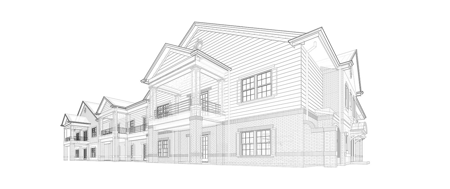
Home Renovation – Step by Step Guide

Home renovation is without doubt one of the best ways to get the home you want.

It can also make you a good amount of money when you come to sell too, if done right.

And therein lies the crucial word: Done right.

Renovating a house can be costly when mistakes are made and hugely stressful, too.

The answer?

Proper preparation and planning – and that’s where our step-by-step guide to home renovation comes in…

Renovating a house: Where to start

When taking on a renovation project knowing where to start can be tricky.

To begin with, you should consider whether a renovation project is right for you in the first place.

If you’re sure it is, being sure what you want to achieve from your renovation is key and part of that comes from knowing and understanding the property you want to remodel…

How old is my house?

If you’re wondering how to find out how old your house is, it’s actually a pretty easy process.

Knowing a little bit about your property before you begin refurbishing it will help you get the best result.

To find out how old your house is, the best place to start is the Land Registry.

The Land Registry holds records of all land in England and Wales, but your local authority could also be a good place to glean more information about your property, too.

Renovating a house: Step-by-step

1. Find the right renovation project

The first thing you’ll need when undertaking a home renovation is a home!

But finding the right property to renovate isn’t always easy.

You’ll need a property that will work for you once work has been completed, but also one that will hopefully see you make a profit when you do eventually come to sell it.

It’s easy to spot a property in need of work simply by looking through the online portals like Rightmove and Zoopla.

But that doesn’t always mean value for money – particularly if the property is on a road with a ceiling price.

When looking for a property to renovate, you should always: 

  • Look at any work neighbouring properties have had done, like extensions
  • Consider the outdoor space to the rear and sides if you’re planning an extension – is there enough room?
  • Research the most recent sale prices in the road and check out any work that has been done at those properties to establish if the road has a ceiling price
  • Have a survey done on the property you’re looking at – a surveyor will check for major, potentially costly problems like subsidence, damp or drainage issues
  • Obtain a building report, which will tell you which construction methods were used throughout the house so you can plan how you’ll renovate the property
  • Get a measured survey, which will provide detailed drawings of the property’s layout – you’ll need this for any planning application

2. Do you need planning permission?

If you’re planning major work as part of your renovation, you may need planning permission.

This can take time, so establishing if it’s required early in the renovation process is key.

So, do you need planning permission?

If you’re not changing the outer footprint of your property, there’s a strong chance you won’t need planning permission.

You will almost certainly need building regulations approval for any structural work or electrical installation, though.

A lot of work can often be carried out under permitted development, including:

  • Single storey extensions
  • Loft conversions
  • Conservatories
  • Porches
  • Decking
  • Basement development
  • Parking

The best thing to do, though, is to always check with your local authority whether you need planning permission or not for the work you wish to carry out.

3. Decide what’s staying and what’s going

When undertaking a large-scale renovation, it can be easy to fall into the trap of stripping a house back to its bare bones.

And while turning a property into a shell can enable you to tackle every area with your own touch and taste, it will also mean more expense – when there could be elements of your property you should keep.

Before starting out with major work, think about your property’s original features and how you could use them with the plans you have in mind.

Not only will keeping some things save you money, it could also help preserve the character of your property.

Think about whether you should keep:

  • Doors
  • Windows
  • Fireplaces
  • Decorative features like coving
  • Beams

4. Schedule of works example

When renovating a house, you’ll require a clear schedule of works.

This is essentially a list of every job that needs to be done during your renovation project, listed in order.

When working with a builder or contractor on a home renovation, a schedule of works also acts as a loosely binding contract between you, the homeowner, and the person doing the work, helping you ensure everything remains on track and within budget.

Here’s an example of a schedule of works for a fairly large renovation project:

External work

  • Brickwork and pointing to match
  • Render and paint exterior
  • Clean, repair and replace roof tiles where needed
  • Repair chimney where needed
  • Repairs to render on front elevation
  • Replace front elevation windows x4
  • Full clean of render to side elevation
  • Replace frosted window to side elevation
  • Remove climbing vegetation to rear elevation
  • Replace rear elevation windows x4
  • Remove sliding doors to ground floor kitchen and replace with French doors

Internal work

  • Remove all carpets on ground floor and replace with supplied wood flooring throughout
  • Remove kitchen and internal wall between kitchen / dining room
  • Remove radiators and replace with new wrought iron rads
  • Fit new kitchen and appliances
  • Remove existing fire surround, plaster wall and make good
  • Remove all carpets on first floor
  • Remove internal wall between bedrooms four and five, plaster walls and make good
  • Remove existing first floor bathroom suite, tiles and flooring
  • Fit new bathroom flooring, tiles and suite
  • Remove existing front door and fit new composite door
  • Remove all rubbish and skip
  • Lay new resin driveway to front

5. Access to your property

Major renovation work requires major machinery.

So, before you start any work, you’ll need to establish, with your builder or contractor, how they are going to get large machinery on to the site of your property.

You may also have to speak with your neighbours if access is required via their land or if machinery access will impact on them in any way.

6. The work begins

This is where your schedule of works becomes to the go-to document for your home renovation.

Once your property is stripped back and ready to be remodelled or any extension built, your builder or contractor will move on to what’s known as first fix jobs.

These include:

  • Removing or adding internal walls
  • Adding door linings
  • Adding floors
  • Adding window frames and units
  • Fitting plumbing structures like soil pipes and drainage connections
  • Fitting items that will sit behind plastered walls, like ducts, alarms and wiring for things like heating thermostats
  • Once the first fix stage is complete, your property’s walls will be ready for plastering and any floor screed will be laid.

Second fix jobs come next and include:

  • Fitting light fittings, sockets, TV and phone points
  • Door hanging and fixing of architraves
  • Bathroom and kitchen fitting installation
  • Fitting all radiators, boiler system and controls
  • Installation of kitchen
  • Boxing in and plastering any exposed pipework

7. Snagging

If you think of your home renovation like a major surgical operation, it should come as no surprise that your property needs time to recover from lots of renovation work.

And during that time, problems can occur, including:

  • Newly plastered walls cracking
  • Minor leaks
  • Heating system issues
  • Decorative scuffs and scrapes

Your builder should honour any snagging issues and return to rectify them after the house has settled for a few weeks or months at no extra cost.

House renovation costs

How much your property renovation will cost depends on a whole multitude of factors.

Firstly, the amount of work you’re undertaking and the time it will take.

Secondly, your budget will be affected by any issues you encounter during the renovation – all houses can have gremlins and surprises lurking, so you should always expect your budget to be tested no matter how prepared you are.

Generally, though, these are the figures you should expect to pay for some of your renovation work:

Extension: £25,000-£50,000

Loft conversion: £40,000

Bathroom renovation: £6,000-£10,000

Kitchen renovation: £7,000-£15,000

New windows: £400-£600 per unit

New heating system: £4,000

Your renovation questions answered

In what order should I remodel my house?

The order in which you undertake work to remodel your house is key.

Generally, most renovations will follow this order of work:

  • Strip out and removal
  • Structural work – floors, ceilings, walls
  • First fix work – plumbing, heating wiring
  • Plastering, flooring
  • Second fix work – plumbing, heating, wiring
  • Bathroom, kitchen fit-out
  • Decoration

How do I start my renovation?

The first place to start when renovating a property is communication and learning.

No tools should be picked up until you have spoken to builders and architects, the local authority regarding planning permission or until you have a plan for what you want to achieve from your renovation.

How do I plan a home renovation project?

The best way to plan a home renovation project is to spend plenty of time considering all the options for work.

Then speak to a number of builders before opting for the best fit.

Once you have your builder in place, draw up a clear schedule of works so everyone involved in the project is abreast of what’s expected and the timeframes for work.

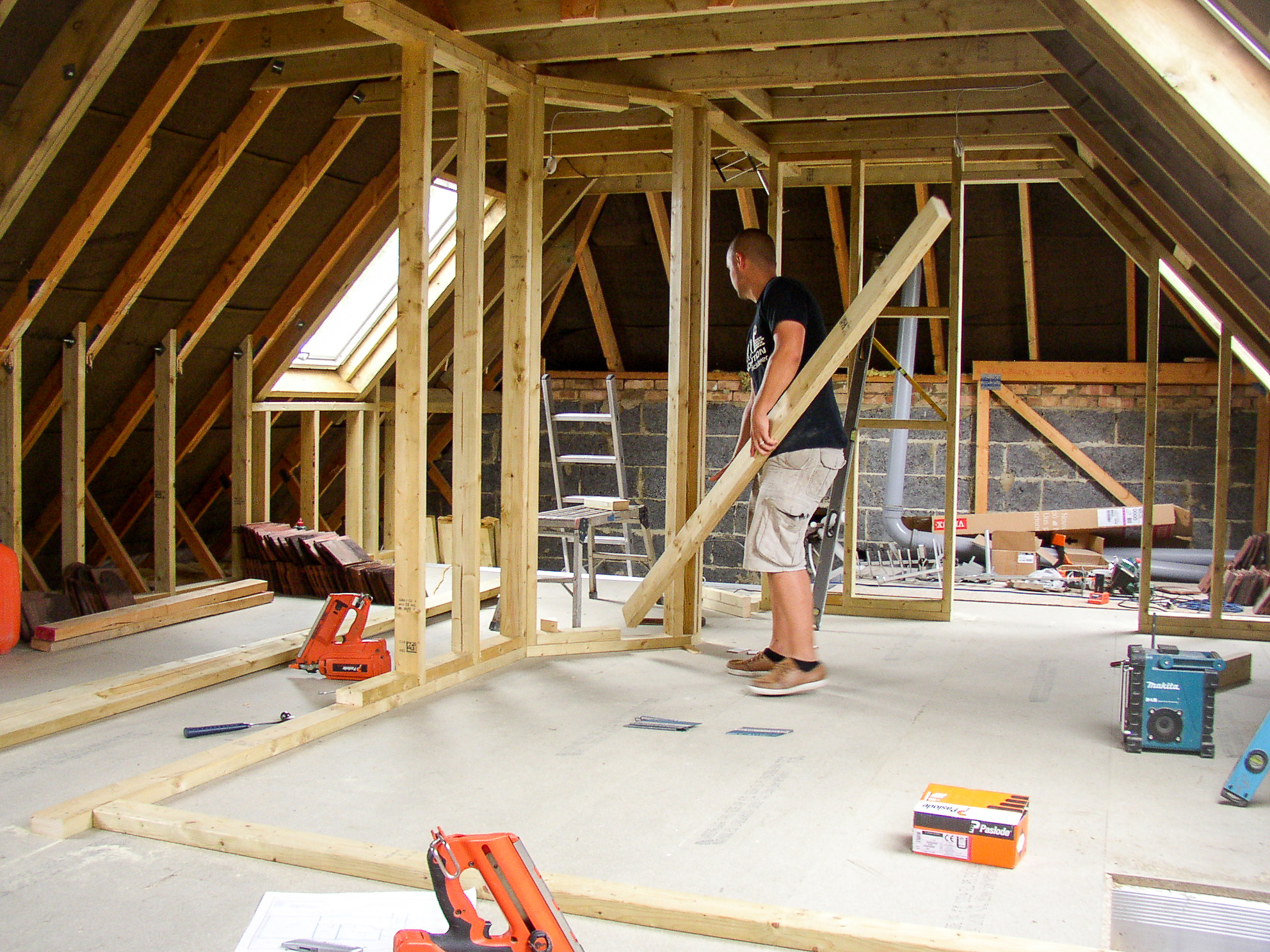
What does STATUS A, B, C & D mean?

Within a construction project and the commissioning process, documents [technical, drawing, method statement, etc] that are utilized for conveying detailed information from or to the manufacturers, site teams, design, and commissioning teams will need to be issued for approval, reviewed, and provided a status from the client team.

This is to accept that, what is being provided is in line with project/design and contract requirements, for works to commence.

Below details the Status, Review Process, and Types of Documents that would generally need to be provided for comment/approval.

We generally have come across two different types of status on projects:

  • The first is where a Status of A, B, C is given
  • The second is where a Status of A, B, C & D is given

Whilst the two look similar there are slight differences.

The below table details the status of documentation and what they can mean on a project. As can be seen the Status D, is basically included to provide the reviewer with an ability to fully reject a document. It usually means that the submitted document does not meet what the title is, is completely inadequate to explain or describe what its intended for, or there is significant information and data missing.

StatusStatus A,B,CStatus A,B,C,D
ADocument reviewed

No comments

Works can commence
Document reviewed

No comments

Works can commence
BDocument reviewed comments noted

Works can commence taking onboard comments
Document reviewed comments noted

Works can commence taking onboard comments
CDocument reviewed comments noted

No works can allowed to commence

Revise and reissue document for approval
Document reviewed comments noted

No works can allowed to commence

Revise and reissue document for approval
Dn/aDocument reviewed

Not meet any requirements of project

Fully rejected

No works can allowed to commence

Revise and reissue document for approval

Status A, B, C & D Table

What is the Review Process?

The review process is usually pretty straight forward as noted below:

  • General Contractor / Main Contractor and their teams create the documentation / information.
  • Internal Review conducted by Main Contractor Engineers.
  • If internal review ok, then issue to *client team via email or some form of electronic platform such as Aconex / Asite / Procore etc.
  • Client team review and provide comment / approval based upon Technical, Installation, Commissioning & Maintainability.

*The Client Team would consist of the Client, Project Manager, Designer, Commissioning Consultant, Facilities Team etc. [if on board early enough].

What types of documents are usually issued for review?

Which documents will require to be issued for approval, will generally be dictated by the specific project/contract documents. But as an outline, the following types of documents would usually be needed relating to the commissioning process [note this is not a fully concise list and just provides an example.

Material/Technical Submissions

These are generally focused upon items of equipment and materials that will be selected and manufactured to meet the design requirements as set out in the project specifications. The materials and equipment can range from details of pipework/cables to generator and chillers.

Material Submissions are usually issued by the general contractor / main contractor for approval by the design team. The commissioning manager should also support in reviewing these documents.

Drawings 

The designer will usually issue a full set of design drawings to the project – these will detail the expectations relating to what should be installed where, sizes, flow rates, and any simple control logic, etc. The general contractor / main contractor would take these drawings, fully coordinate the services, and produce ‘shop drawings’ / ‘working drawings’.

These shop/working drawings should be reviewed and commented upon by the project team [designer, commissioning consultant].

Testing Procedures 

Testing procedures should be developed by the General Contractor / Main Contractor for the future commissioning works – these will range from early testing requirements such as Weld / Pressure Testing all the way through to the final building-integrated testing.

These testing procedures should be reviewed and commented upon by the commissioning consultant, coordinating with other team members such as the designer and facilities staff.

Testing Sequence and Programme

The expected testing program and sequence of works should generally be developed by the general contractor / main contractor.

This testing program/sequence should be reviewed and commented upon by the commissioning consultant, coordinating with other team members such as the designer and facilities staff.

Phase 1-4 Site Investigations

Phase 1 Site Investigation

Phase 1 Site Investigation or Preliminary Risk Assessment (Desk Studies) are an integral and founding part of the site investigation process.  They are used to create a preliminary Conceptual Site Model (CSM) in order to identify any potential pollutant linkages.  The CSM is then refined and conclusions and recommendations are provided.

The desk study process involves putting together a picture of a sites environmental setting by collating site specific data and information which includes the geology, hydrogeology, hydrology, site history, mining & quarrying, landfill & waste, and any regulatory concerns from statutory bodies such as the Local Authority and the Environment Agency. This allows our team of Environmental Consultants to build a picture of a site by identifying any potentially significant features such as potential contamination sources, pathways and receptors, and subsequent ‘pollutant linkage’; where all three must be present for a pollutant linkage to exist. If present, then further investigation would be required (see our page on Phase II Site Investigations).In addition to the above our Phase I Site Investigations also identify the anticipated ground conditions beneath any proposed buildings for geotechnical purposes.

Phase 2 Site Investigations

Phase 2 Site Investigations are the second stage in the site investigation process, where the results and recommendations presented in the Phase 1 Desk Study outline the requirement for further investigation. This is usually a ‘preliminary investigation’ by way of intrusive ground investigation using a combination of various techniques depending on the potential risks identified during the Phase 1 Desk Study. GeoCon are experts in ground investigations for all types of sites and projects including contaminated land, proposed roads, bridges and infrastructure, areas of former mining, areas of landfill and much more.

Phase 2 Site Investigation techniques include hand pitting, machine excavated trial pitting, window sampling and windowless sampling, cable percussion boreholes, rotary open boreholes and rotary cored boreholes. Each technique is used for different applications and a typical ground investigation may comprise a combination of the above techniques depending on factors such as sources / receptors, geology / hydrogeology and access constraints. The ideal Phase 2 Site Investigation would be designed to collect information on a site as a whole for both geoenvironmental and geotechnical purposes, this is the most cost effective as it reduces the potential for repeat investigation, during a site investigation samples would be collected for chemical testing and geotechnical testing.

Standard practice would be for one of our specialist engineering geologists to design the preliminary site investigation using targeted and non targeted methods to achieve a good overall coverage of the site and to target any potential sources. The results of this investigation would usually be enough to determine a sites suitability for use and in some cases may outline the requirement for further work or Phase 3 Site Investigation.

By undertaking a Phase 2 Preliminary Site Investigation, it allows us to keep costs down for our clients as most sites would not require a Phase 3 Detailed Site Investigation.

Phase 3 Site Investigation – Remediation

Remediation is the act of rendering a site ‘fit for purpose’ under the National Planning Policy Framework (NPPF). In its broadest definition, it’s taking previously developed land and making it suitable for redevelopment, in its many forms. The term remediation covers many activities and even more solutions and is generally only applicable in land development projects.
Here at GeoCon we specialise in a variety of remediation related services, but mainly that of chemical contaminants from site related sources or more what is more generally known as “contaminated land”.

Contamination remediation can range from the very basic: complying with the BRE cover system approach, to the more complicated, such as bioremediation; and can be achieved in a day or over several years depending on the size of the site and the approach adopted. We have a wealth of experience of remediation design, management and supervision; all the skills needed to support a project through the remediation process. Taking the findings of a site investigation GeoCon will consider the options available to break the pollutant linkages associated with a site and formulate a remediation strategy to achieve that requirement. Not only that but with our links throughout the sector we can advise on suitable remediation contactors, many of whom we have first hand experience of working with.

Not as extensive as remediation of contaminated soils, but just as important, is that of the remediation of contaminated controlled waters, either groundwater or surface waters. With the contamination of controlled waters being, by its very nature mobile, this poses a different approach to contaminated soil remediation. Again, our depth and breadth of experience puts GeoCon in an ideal place to design and manage remediation projects for controlled waters.

The final aspect of contaminated land associated remediation that we at GeoCon carry out is that of remediation of hazardous ground gases. Whilst we can advise on the building protection measures, we are not design engineers so it is important to appreciate we cannot design gas related building protection measures. Rather, in this scenario, we can advise on external gas control measures, such as: passive and active land venting systems; barriers and trenches; and active and passive gas collection systems.
Remediation of contaminated soils and controlled waters along with hazardous ground gas remediation would be handled here at GeoCon by our team of environmental consultants.

Phase 4 Site Investigation – Validation

Whilst remediation is the act of rendering a site ‘fit for purpose’ under the National Planning Policy Framework (NPPF), validation is the process by which the evidence is gathered and presented to verify that the proposed and agreed upon remediation strategy has been carried out. Here at GeoCon we specialise in a variety of validation related services, but mainly that of chemical contaminants from site related sources or more what is more generally known as “contaminated land”.

Validation, also known as Verification, is a reactive process and is difficult to predict the duration and extent of the involvement of the independent assessor, such as GeoCon.  On this basis, based on our experience, we offer our clients a budget based on anticipated workload and provide regular updates as to how the work / budget is progressing through the validation process.

For short term remediation projects such as adopting a BRE cover system, validation can even be carried out upon completion of the remedial activity.  The downside of this approach is that we would need to advance validation hand pits in the finished conditions and all the potential disturbance that would entail.

It is more usual to provide a ‘watching brief’ during the remedial work and report accordingly.

When dealing with a cover system remediation, none of this negates the need to confirm that any material brought onto site for use in soft landscaping areas (e.g. gardens) is, itself, also ‘fit for purpose’ and suitable for use in its intended location.  We would always need to collect validation samples for the imported material.

Validation of groundwater remediation is a long-term commitment, as generally, the processes adopted for groundwater remediation are long term in themselves.  Quite often validation of this process is achieved by showing a reduction in concentration of the Contaminant of Concern over time with a prediction of when full validation will be achieved, a process of monitored attenuation.

Window Sampling & Windowless Sampling

Window sampling or windowless sampling is a technique used to bore through shallow soft soils to investigate the substrata in order to gain a profile of the ground conditions and to facilitate soil sampling for chemical and geotechnical analysis.

Window sampling is usually carried out by a Premier, Terrier, Competitor or Competitor Dart type machines which are capable of boring up to 10.00mbgl depending upon soil type but are generally restricted to Circa 5.00mbgl.  Window sampling machines have the facility to take U100’s, U38’s and STP’s (Standard Penetration Tests).

Window sampling can be used for the investigation of contaminated land, for geotechnical investigations and for the installation of ground gas and ground water monitoring wells.

These rigs are particularly good for investigating in areas of limited access, and even have the capability to remove the front mast to squeeze into tight spaces.

In addition to the standard window sampling machines, hand held equipment is available for difficult access such as embankments or basements.

https://www.geoconsiteinvestigations.com/gi-contractor/window-sampling#:~:text=Window%20sampling%20or%20windowless%20sampling,for%20chemical%20and%20geotechnical%20analysis.

Steel-fibre-reinforced concrete

Design of steel-fibre-reinforced concrete is not covered by design standards such as BS 8110 (now withdrawn) or Eurocode 2, which assume the use of bar reinforcement.

Various design approaches are currently adopted.

The first may be described as Design on the basis of material properties. In this approach, material properties such as residual tensile strength are determined from standard small beam or statically determinate slab tests. These properties are then inserted into equations determined mathematically or empirically that define the performance of the concrete element to determine the load capacity. In general, the design equations will be linked to properties determined from a specific test.

This approach is discussed in detail in Concrete Society Technical Report 63, Guidance for the design of steel-fibre-reinforced concrete.

Other approaches are commonly used, such as Design assisted by testing. This approach has been used widely for the design of pile-supported slabs and more recently has been used for fully suspended slabs. The basic premise is that the performance of the concrete in small beam tests, while satisfactory for linear elements, is not representative of the performance of elements such as slabs. Thus, the process consists of testing round indeterminate slabs to determine the design flexural resistance. The slab can then be designed by yield line theory. This design procedure is justified by the results of load tests on large-scale sub-assemblies of suspended slabs.

A partial application of this approach is the design of composite slabs on steel decking where tests to determine the local performance of fibre-reinforced concrete, e.g. around stud shear connectors, have been used to demonstrate that the performance is adequate. Slabs with fibre-reinforced concrete can thus be designed in accordance with the Standards for composite slabs with fabric reinforcement. The approach is approved by SCI (Steel Construction Institute) for specified combinations of steel fibres and decking.

Design by performance testing, or proof testing, is applicable to precast units where a large number of items are required for a particular purpose. The element’s dimensions, fibre content, etc. will be determined on the basis of judgement or experience. Representative completed units will be tested to demonstrate their ability to carry specified loads.

fib Model Code for concrete structures (2010) contains some clauses for design.

The 4th edition of the Concrete Society report TR34 Concrete industrial ground floors (2013) provideds a design approach for warehouse floors.

Swedish Standard SS 812310 Design of fibre concrete strcutures (in English), which is complementary to Eurocode 2, is due for publication in 2014

The Difference between Planning Permission and Building Regulations Approval

Ever wondered about the difference between planning permission and building regulations approval?

Very often home owners, business owners and property developers are confused by the need to obtain approval from the council for their building work. Does this sound like you?

The fact is that Planning applications and Building Regulations (Building Control) applications are considered under different laws.

  • So what is the difference between planning application and building control application?
  • Do you need to make both applications for your project?

Here’s the answer: Planning permission covers the principles of development assessing whether the development will accord with local and national policies and whether it would cause unacceptable harm, for example, to neighbours’ amenities, whereas the building regulations cover the structural aspects of development and progress throughout the construction.

So… When you make a planning application you are seeking permission to enable you to carry out development. On the other hand, when you make a building regulations application you are seeking to have the details of your development checked and approved for compliance with the standards of construction. That is the main difference between planning permission and building regulations.

Planning permission and building regulations approval (building control) are different and they are two separate pieces of legislation. Sometimes you may need both; sometimes you may only require one; or none at all. Because the planning legislation is distinctly different from building control legislation, it should not to be assumed that one grants consent for another.

What is Planning Permission?

Planning permission controls the way our towns, cities and countryside develop. This includes the use of land and buildings, the appearance of buildings, landscaping considerations, highway access and the impact that the development will have on the general environment.

The government gives Local Planning Authorities the power to manage where people build and what they do with land. The Development Management team of Local Planning Authorities handle planning permission applications.

Planning permission is needed for most types of new development or changes to the use of land. Conservation areas and listed buildings also have specific requirements. So it is always best to consult an architecture company before taking the step forward.

How to make a Planning Permission application?

When making a planning application, it is important to make sure that a fully completed set of forms is submitted. Accurate scale drawings should accompany all applications. These should include Full set of Planning Drawings, Design & Access Statement Report and Duly Completed Application Form.

The drawings should indicate all architectural features including walls, windows, doors, rooms, building and ceiling heights and materials. A Design and Access Statement report is also required with planning applications for most types of new developments or change of uses to justify how design standards and planning policies are met.

But here’s the funny thing: In addition to the Government’s national requirements, most of the councils have different local requirements for applications of a particular type, scale or location. You must include all the necessary information with your planning application. If you do not, your application cannot be validated.

Securing planning permission is NOT rocket science but it imperative to seek professional help from an architect when preparing Planning applications. No matter how good your own design instincts, a qualified professional, an architect or a planner, will help you avoid major mistakes and handle the complex technical questions associated with your application.

What is Building Regulations (Building Control) approval?

Building regulations (building control) are standards that apply to all buildings to make sure they are safe for people who are in or around them. The Regulations are a series of Approved Documents covering the technical aspects of construction work.

Most building work whether new, alterations or extensions or change of use require building regulations approval. Examples of when building control approval is required include but not limited to building extensions and loft conversions, converting garages into a habitable room, carrying out certain structural alterations, installing cavity insulation, changing the use of a property, underpinning and carrying out drainage works.

How to make a Building Regulations (Building Control) application?

Each local council in England has a building control section. The local council has a general duty to see that building work complies with the building regulations.

As an alternative to gaining approval from Local Authorities, the Government has introduced legislation to allow private Approved Inspectors to check work requiring building Regulations approval. You are free to choose which type of building Control Body you use on your project.

Let’s dive in…

There are two ways you can make a building regulations application, either by making a Full Plans application or by submitting a Building Notice notification. A Full Plans application will consist of detailed plans and full specifications of the construction details together with the appropriate fee.

Or you would use a Building Notice if you are doing simple work to a domestic building. A Building Notice application doesn’t generally require the submission of detailed plans or full specifications of the construction details. However, you will not receive the protection and reassurance that an Approved Plan would give you, and the whole process of making sure your work complies with the building regulations is carried out at the site inspection stage.

Now: Whether you are renovating your home from scratch, converting your property, or simply adding an extension, you will need a structural engineer proficient in preparing your structural drawings, calculations and specifications for your building regulations application.

What is the difference between Building Regs and Planning Permission?

If you want to renovate a new home, there is a good chance you will need some form of permission before starting any building work.

 There are two main types of permission, Building Regulations (building regs) and Planning Permissions and if you are doing any extension work, you may need both.

 Building Regulations set the minimum standard for the design and construction of buildings to ensure that any work has been done correctly. They cover safety standards for the construction of everything from staircases and chimneys to the heating efficiency of boilers and providing access facilities for the disabled. You may need building regulation approval to cover work on your home both internally and externally.

Planning Permission or Building Regulations

 Planning Permissions are more about the external appearance of the building and making sure any landscaping considerations are in keeping with the local environment. Ultimately, Planning Permissions are there to avoid architectural ‘eyesores’ and oversized extensions being built that would be ‘out-of-keeping’ in an area.

 Both are legally required and must be submitted to your local council before beginning any work. Failure to comply could lead to a fine.

 What are Building Regulations?

Before you carry out any building work, you or your builder/architect/surveyor must submit full plans for approval to your local council’s building control team or through the buildings notice procedure. Some examples of what building regulations cover, include:

  • Structural stability of a building.
  • Correct Fire Safety measures including fire escapes.
  • Ensuring a building is water and weather tight.
  • The use of toxic substances in cavity fill insulation systems.
  • Levels of sound insulation between buildings and rooms.
  • Technical design standards for sanitary pipework and drainage.
  • Underpinning the foundations of a building.
  • The design, installation, inspection and testing of electrical installations. 

What is Planning Permission?

If you are planning to build a new home or alter the appearance or scope of your home, getting planning permission is one of the first hurdles you will have to face. They are many different types of permission and your architect or builder will be able to help you determine which ones apply to your property project.

 The main types of Planning Permission include:

Householder Planning Consent – Required for extensions, conservatories, loft conversions, dormer windows, garages and out buildings.

Full Planning Consent – Required if you are planning on changing the number of dwellings on the site, or changing the use of a property. You do not need planning permission for many internal renovations.

Outline Planning Consent – Find out if the scale and scope of your plans are likely to be approved in principal before you commit to any substantial costs.

Planning Permission in a Conservation Area – If you live in a conservation area, you will need planning permission before any relevant demolition of property.

Listed Building Consent – If your property is a building, object or structure judged to be of national architectural or historical interest, then you will be subject to extra conditions before any work can begin.

Lawful Development Certificate – For peace of mind that an existing or proposed work is lawful, or that you do not need planning permission, you can apply for a Lawful Development Certificate or LDC.

Retrospective Planning Permission – If you have made changes to your property without getting planning permission, you can make a retrospective planning application for work you have already carried out.

“factual” vs “interpretative” geotechnical report

“Ground Investigation Reports” (GIR) and “Geotechnical Design Reports” (GDR)

One of the things I’d like the most about my job is the fact that I still learn new things, even on topic were I wrongly believe there is not much more new to see.

This week during a telco with my accomplice in crime Eduardo I’ve discovered a new trick that I suspect has been invented by someone in the US (or possibly in the UK) – the split between “factual” and “interpretative” geotechnical report.

In the countries were I’ve worked until today, the geotechnical survey is usually a huge package of documents full of formulas, picture, diagrams and numbers. I’ve been never touched by the idea that part of the content was somehow different.

However, I’ve discovered that somebody (I bet a lawyer) introduced this categorization.

The Geotechnical Data Report (AKA the “Factual stuff”) would be the part including things like:

  • Pictures
  • Boring logs
  • Trial pits logs
  • Field test (SPT, cone penetration, etc.)
  • Laboratory data (water test, CBR, etc.)

This is the type of things that could safely land in a contract and that should be shared and used by the subcontractor.

However, a civil engineer would like to see other information to do his work. He would expect the type of information that should appear in the Geotechnical Interpretative Report (AKA the “don’t rely on me stuff”), with things like:

  • Ground behaviour of geotechnical units
  • Slope stability
  • Seismicity
  • Geotechnical cross sections
  • Construction methods and proposed technical solutions

Basically, nothing connected with design and construction.

Know you know that, wherever possible, you should ask to the geotechnical survey company for the full package (factual + interpretative) but keep them separate – at least if you face a big project with a high geotechnical risk.

Said that, I also want to reiterate my opinion that a good geotechnical survey can make the difference between a successful project (at least for roads and foundations) and a nightmare project with claims and over cost.

It might be difficult to find the budget for this kind of investigation in the early phases of the project but believe me, it’s worth every euro that you will spend on it.

42 Types of Drawings Used in Building Design

Making a construction plan before beginning the construction is imperative. It provides a detailed overview of the building. Keeping that in mind, a different types of drawings is used today for this purpose. Apart from providing the technical details in a readable format, these drawings are also essential to get the project approval.

They set a benchmark for the construction process and assure compliance to the building standards.

It can be said that these construction drawings provide an outlet to the architectures to convey their ideas and concepts regarding any building.

Types of Drawings Used in Building Design

Listed below are the majority of the construction drawings. All the types of construction drawings can be segregated into the following sets of drawings:

  • Architectural Drawings
  • Structural Drawings
  • HVAC Drawings
  • Electrical & Plumbing Drawings
  • Firefighter Drawings
  • Miscellaneous Drawings

Architectural Drawings

Architectural-Drawings_42-Types-of-Drawings_Guide_United-BIM

Architectural drawings are the technical representation of a building that is made prior to the beginning of the construction process. They are made with lines, projections and are based on a scale. Different types of architectural drawings include:

1.

Site Plan

A Site Plan is an aerial view of the construction site that includes the primary building and its adjoining constructions. Among its wide applications, we can include construction drawings for building improvement, understanding the scope of construction activities. Along with it, it helps identify the topography of the building including roads, pavements, etc.

2.

Floor Plan

These are an in-depth version of the room layout. Floor plans are made irrespective of the fact that they are to be utilized during the construction of a home, shop, or a commercial project. Applications include an understanding of the dimensions and different kinds of installments. This helps get an idea about the usage of the limited room space.

3.

Cross Section

Cross sections allow the architect to look at the different components of a building vertically. This 2-dimensional imagery is useful to provide an overview of both the visible and hidden components in a building. Another type of cross-section is Wall cross-section that is useful to get a view of both sides of the wall.

4.

Elevation

Elevations help an architect understand the facing of the building. It is useful to know about the direction of the sun and the wind corresponding to the building. They also indicate the height of the building, the external and internal marking which includes the doors and sizes of the windows too.

5.

Landscape

The landscape plan is the aerial of the whole area in which the building is built. It includes the areas designated for trees, street lights, parks, pools, and everything else. Landscape plans are more often used to depict the external aesthetics of the building. You can also include in them the paths, roads, pavements, parking areas, and whatnot.

6.

Finishing Drawing

The Finishing drawing has a close relationship with the elevation drawings as they also talk about the smaller details of a building. Among the various types of finishing drawings, you can include the patterns of the floor, type, and shape of false ceiling, paint colors, plaster, textures, and whatnot. They are important to maintain the aesthetic value of the structure.

7.

Working Plan

The designers create working plans or construction plans for the contractors to help them understand the scope of the project. The benefits of such a plan include the convenience to fabricate the construction material according to the overall design. Working drawings also include a legend that provides information about the different components.

8.

Section Drawings

As the name suggests, the section drawings show the structure in a sliced form. This kind of construction drawing helps identify the primary structures in relation to other surrounding structures of the building. Further, section drawings also provide information for the types of materials to be used in the construction.

9.

General Note

The general note does not have any drawings. It contains detailed information about the buildings. This includes the by-laws, codes, length, mapping forms, construction type, legends, abbreviations, and everything else that is essential.

10.

Excavation Drawing

Excavation drawings are needed to know the length, depth, and the width of the building excavation. It talks about the extent of excavation, removal of soil, and the process of excavation. The different processes used for excavation comprises of trenching, wall shafts, tunneling, and others.

11.

As-Built drawings

The As-built drawings provide a comparison between what has been built and the original plan. It may happen due to circumstantial conditions the contractors may have to change the construction pattern and design. The As-built drawings are made either during the construction process or after the construction is complete.

12.

Line Plan

These are the single line depictions of the structure of a room. The lines are drawn exactly as the different configurations of the room will be. It has the sizes of the rooms, the position of the doors with proper labeling. A line plan provides an overview of how the whole room will be planned out.

13.

Shop Drawings

Shop drawings are also a sort of construction guide that personifies how an object has to be installed, fitted, or manufactured. Most of the time, the shop drawings are prepared by contractors and subcontractors. Also, suppliers, manufacturers, and fabricators can prepare these drawings. Shop drawings ensure compliance with the original design and specifications of the object.

Follow these:Tips to create accurate Shop-drawings

14.

Installation Drawings

There are plenty of installations that can be added to a building. Some are essential, like the ventilation, heating, and cooling system. So, in that matter, a plan to help with all kinds of installation can be useful to the contractors and the development team. From the most complex structure like data centers to control rooms, these kinds of drawings are also essential from the management point of view.

15.

Location Drawings

Location drawings are also referred to as general arrangement drawings. They are made to showcase the composition of the entire project. And if that project has several parts and buildings to be constructed, a location drawing will include details for all of them. Under it, you may consider adding elevations, projections, different plans, and sections.

16.

Location Plan

The location plan further covers a wide area. This kind of construction drawings requires the architect to check out the whole area where the building is to be constructed. Also called General Arrangement Drawings, they represent the objects and more importantly, they show the relationship between the different stages of building development.

“Life is the Art of Drawing Without an Eraser” — John W. Gardner

Structural Drawings

Structural Drawings are also called engineering drawings and they focus on the structural aspect of the building. These drawings are included in the proposal documents and act as a guide for the workforce.

17.

Column Layout

Column layout reinforces the design and pattern of the columns of the whole structure. This plan is divided floor wise and demarcates the exact size and distance between every column of the building. Column layout drawings further make it easier for the contractors to make sense of the whole building layout.

18.

Plinth Beam Layout

Plinth beams are yet another form of beam structures that reinforce the support system of a building. The plinth beam layout drawings showcase the position, length, and sectional design of the plinth beams. Here too, the plinth beams drawings are also made floor wise.

19.

Lintel Beam Layout

Lintel beams are yet another form of support structures that are made above the doors and windows. These are reinforced structures that are made to provide strength to the part of the building that is made above the windows and doors. In these kinds of drawings, you will find the correct positions, dimensions, and the number of lintel beams on every floor.

20.

Roof Beam and Shuttering Layout

A roof beam is made to strengthen the building’s overall structure. A roof beam is a triangular structure that is usually made on the top of the building and supports the roof. Roof beams are usually made out of wood, but it can also be made from steel or concrete.

21.

Roof Slab Layout

Roof slab layout is more prominently made in the AutoCAD architectural software. The main purpose of the roof slabs is to provide a detailed account of the floors, roof faces, and other such surfaces that require precise edge information.

22.

Block Plan

A Block plan is the representation of a wider area that is in proximity to the main building under construction. A block plan may include the adjoining buildings, the roads, boundaries, and other such components. More importantly, a block plan is represented in scales, which also means that they cover a wide area.

23.

Framing Plans

Framing plans are similar to the beam layouts. They offer information about the framework, sizes and positions of the beams. Framing plans are helpful to the builders as they can easily understand and lay out the plans for the roof, floor, and other such structures that are an essential part of a building.

24.

Component Drawings

The component drawings are majorly referred to as the drawings supplied by the manufacturer of a product. These kinds of plans are replete with the drawings of the component thus providing a detailed insight into its markings and different sub-parts.

25.

Concept Drawings

Concept drawings are more like the first draft of a construction project that is made in the first instance. They are not very detailed or distinguished. The concept drawings are like rough sketches of the building and the nearby areas. They are more prominently used to describe an overview of the building to potential clients or stakeholders.

26.

Engineering Drawings

Any building may require the installation of some engineered objects or components. So, an engineering drawing is targeted towards the convenient construction or placement of these kinds of structures. They are more of a guide to help the contractor and the engineer, they work in sync with each other and get the desired results.

27.

Assembly Drawings

In the construction industry, these types of drawings are made to depict the connection between two components of a structure. It shows how the different parts of this structure fit together. It has all kinds of designs and patterns including 3D, sectional, and elevation views.

28.

Design Drawings

The design drawings are somewhat similar to concept drawings. This means that they are also useful in case of fetching new conversions for a particular project. They are also useful in proposing the designs to the stakeholders and then providing a rough idea to the designing teams for their reference. Design drawings can also become a benchmark or can be used as a comparison.

Close Proximity Piling

Through the use of DAWSON-WAM’s relatively silent and vibration-free pile installation we can offer a virtually zero tolerance installation when working adjacent to existing buildings and structures. This can be extremely beneficial to clients in maximising space when working within built up environments such as city centre sites.

The Cased CFA systems operates an offset system where the most outer part of the system is the casing which mean piles can be installed extremely close to existing structures. Typically piles can be installed within 100mm of existing structures where Conventional CFA systems are restricted by the drive motor geometry and require at least 600mm clearance.

For a Client’s peace of mind DAWSON-WAM can carry out all pile testing, vibration & noise monitoring, pile deflection analysis and sensitivity analysis of adjacent structures when completing close proximity works.


We have been working with Toorc Consulting Ltd and Soiltech on producing a new piling rig. As you know building basements with CFA piles is normally the most cost effective solution, however being close to boundaries and tree protection orders causes significant problems with clearances such that you have to either reduce the basement size or opt for the sheet piling zero rig which is very expensive (about twice standard sheet piling rates). Normally you need to leave a minimum 750mm from face of obstruction to centreline of pile thus nearest internal basement wall face to an obstruction is 1200mm or so.


We have developed a piling rig that can now install 450mm and 600mm diameter CFA piles to within 15mm of any obstruction such as boundary walls, TPO’s etc, to a depth of 14.5m. Therefore face of basement wall will be circa 650mm from boundary, adding an extra ½ metre to the basement.  At this depth of pile most residential basements and basement pools can be accommodated.  The rig will be owned and operated by Burras. The motor will not overhang the boundary therefore does not affect party wall awards which is the most common difficulty we face on tight urban sites recently. This is a way of reducing basement costs and maximising footprint on these tight sites.

Joist vs. Rafter

Main Difference

The main difference between Joist and Rafter is that the Joist is a horizontal structural element transferring load from flooring to beams, typically running perpendicular to beams and Rafter is a structural members in architecture.

Joist

A joist is a horizontal structural member used in framing to span an open space, often between beams that subsequently transfer loads to vertical members. When incorporated into a floor framing system, joists serve to provide stiffness to the subfloor sheathing, allowing it to function as a horizontal diaphragm. Joists are often doubled or tripled, placed side by side, where conditions warrant, such as where wall partitions require support.

Joists are either made of wood, engineered wood, or steel, each of which have unique characteristics. Typically, wood joists have the cross section of a plank with the longer faces positioned vertically. However, engineered wood joists may have a cross section resembling the Roman capital letter “I”; these joists are referred to as I-joists. Steel joists can take on various shapes, resembling the Roman capital letters “C”, “I”, “L” and “S”.

Wood joists were also used in old-style timber framing. The invention of the circular saw for use in modern sawmills has made it possible to fabricate wood joists as dimensional lumber.

Rafter

A rafter is one of a series of sloped structural members that extend from the ridge or hip to the wall plate, downslope perimeter or eave, and that are designed to support the roof deck and its associated loads. A pair of rafters is called a couple. In home construction, rafters are normally made of wood. Exposed rafters are a feature of some traditional roof styles.